No audio available for this content.
UAVs, precision agriculture and robotic guidance require high accuracy at low cost.
Emerging high-volume markets call for RTK technologies previously limited to niche markets by complexity and cost. This article discusses design and implementation of a very precise RTK-based module solution while maintaining cost, size and power consumption as low as possible. Several tests under a range of signal environments benchmark the new module’s performance against existing L1 RTK products.
Real-time kinematic (RTK) positioning has matured over the last few decades into a well-understood technology that, to date, has remained confined to high-end applications by high costs and complexity. Meanwhile, the rapid rise of robotic guidance applications has increased the need for higher accuracy for navigation purposes, fostering an ever-increasing demand for affordable and energy efficient high-precision solutions. Here we discuss the challenges associated with bringing RTK technology to mass markets.
The main challenge for any RTK receivers is resolving carrier-phase ambiguities to their integer values. To do so, an RTK receiver needs clean carrier-phase measurements. In general, high-end RTK receivers typically rely on multi-frequency, multi-constellation solutions and complex estimation models to improve ambiguity resolution performance. However, to reduce size, complexity and power consumption, mass-market receivers typically use narrowband single frequency front-ends, which increase noise and code multipath. Furthermore, mass-market GNSS modules have much less processor and memory resources to call upon. Therefore, to fully integrate the RTK engine, mass-market receivers typically need to restrict the computational burden by optimizing complex RTK algorithms.
Here we discuss our efforts to overcome these challenges while delivering centimeter-level positioning. Performance evaluation under challenging signal environments of a new mass-market L1 RTK module is benchmarked against an existing high-end L1 RTK product.
Multi-Constellation Support
A straightforward approach to improve reliability of the ambiguity resolution is to extend support to other constellations in addition to GPS. GLONASS and BeiDou have respectively reached full and initial (regional) operational status offering significant satellite availability improvements. Both systems broadcast their L1 open service signals using a frequency band that is offset with respect to that of the GPS L1 open service signals and, therefore, concurrent reception of GPS/GLONASS or GPS/BeiDou requires two distinct RF paths. Since the new L1-RTK based module can support reception of GNSS constellations using two independent RF paths, RTK support was implemented for both GLONASS and BeiDou, allowing either of these systems to be used with GPS. On the other hand, the low availability of operational Galileo satellites limits the benefits of a GPS/Galileo solution and, therefore, RTK support for Galileo was not implemented.
GLONASS Ambiguity Resolution
The Russian GNSS transmits L1 signals using a frequency division multiple access (FDMA) technique. While this increases the constellation’s resilience to narrowband interference, it creates two major problems for ambiguity resolution. First, GNSS pseudorange and carrier-phase measurements contain frequency dependent biases related to the receiver’s analog and digital hardware. For GPS (and other code division multiple access [CDMA]-based GNSS), all measurements share the same frequency and the biases cancel out during between-satellite differencing. However, this is not the case for GLONASS where the remaining inter-frequency biases are absorbed by the ambiguities, complicating their resolution. Second, GLONASS signal wavelengths are not common for all satellites within the L1 frequency band.
In addition to the double-difference ambiguity, GLONASS double-difference observations also consist of the between-receiver single-difference ambiguity related to the reference satellite scaled by the wavelength difference of the two signals.
Due to a lack of observability, the single-difference reference ambiguity cannot simply be estimated along with the double-difference ambiguity. On the other hand, merging the two ambiguity terms into a modified one results in an ambiguity that is no longer an integer and therefore cannot be fixed.
Both issues are well understood and several methods have been proposed to circumvent them. However, it is not yet clear whether the performance benefits brought by GLONASS ambiguity fixing outweigh the computational overhead.
BeiDou Ambiguity Resolution
China’s GNSS currently broadcasts B1 open service signals using mixed satellite and signal types, which could complicate ambiguity resolution. The limited orbit variability of BeiDou geostationary and inclined geostationary Earth orbit satellites produces poor carrier-phase ambiguity.
Despite this limitation, recent investigations reported very good dual- or triple-frequency GPS/BeiDou RTK performance, regardless of satellite type. Therefore our approach is to estimate BeiDou ambiguities for all satellites using appropriate weighting of the different carrier phase and pseudorange observations.
Cycle-Slip Detection
Single-frequency RTK inherently offers more limited measurement redundancy than its dual or even triple-frequency counterparts, making cycle-slip detection a difficult task. While a posteriori residuals checks provide a powerful mean to detect outliers, they are computationally expensive and therefore can only be used sparingly. To detect cycle slips prior to the measurement update, heuristic checks are performed on innovation sequences and complemented by systematic analysis of phase lock and C/N0 values.
Configuration Trade-Offs
The RTK positioning modules can concurrently receive and track up to two GNSS systems. By default, the reference receivers are configured for concurrent GPS and GLONASS reception. This can be modified to enable the combined use of GPS and BeiDou.
To optimize the use of processor and memory resources, the number of channels has been limited to 20. This is sufficient for dual-constellation operation almost everywhere except for a limited area in Asia where the number of visible GPS and BeiDou satellites can occasionally exceed 20.
Furthermore, the rover receiver can operate in RTK fixed or RTK float mode. In RTK fixed mode, the receiver will try to resolve ambiguities to their integer values whenever possible whereas in RTK float mode, the receiver will keep the ambiguity estimate as a floating number. The RTK fixed mode will provide the highest level of accuracy but can exhibit position jumps when transitioning from a float to a fixed solution or reliability issues when operating in degraded signal environments where multipath can lead to wrong ambiguity fixes. The RTK float mode, on the other hand, will typically provide dm-level accuracy but a much smoother trajectory.
Static Performance Evaluation
The static test data was collected on the roof of an office building in Singapore in April 2016. Twelve hours of data were collected by four receivers connected to a high-precision receiver forming zero-baseline for both GPS/GLONASS and GPS/BeiDou configurations. This allowed a thorough statistical evaluation of the ambiguity resolution performance for both configurations.
Static Data Processing
The static data sets were post-processed with a software using exactly the same algorithms as those embedded in the receivers’ firmware, allowing for direct comparison of different receiver configurations. The time-to-first ambiguity fix (TTFAF) is often used as a key indicator to assess the ambiguity resolution performance. The TTFAF differs from the time-to-first fix (TTFF) in that it only includes the time required by the ambiguity resolution algorithm to converge. To measure the TTFAF, the software is modified to perform a hot start (where position, time and ephemeris are kept) at regular intervals. This is done to increase the data set sample size and to provide a relevant statistical analysis of its reliability and rapidity.
Static Test Results
As expected, FIGURE 1 shows that the use of the GPS/BeiDou configuration significantly improves satellite visibility over the GPS/GLONASS configuration. The average number of navigation channels used is close to 20 when combining GPS and BeiDou whereas it remains below 16 when combining GPS with GLONASS. This produces faster TTFAF in GPS/BeiDou mode (FIGURE 2).
Walk Performance Evaluation
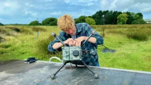
Two walk data sets were collected around Priory Park in Reigate, England on October 2015 and February 2016. Approximately one hour of data was collected each time with the equipment depicted in FIGURE 3. The antenna was mounted on a survey pole to ensure the best sky visibility possible. The radio frequency (RF) signal was then split three-way and distributed to a high-precision receiver, our rover receiver and a record and replay simulator. The RTCM correction stream was generated by a high-precision receiver connected to an antenna located on the roof of an office building and made available on a server. Using a Raspberry Pi and a 3G modem the RTCM stream was forwarded to both our receiver and the recorder. As shown in FIGURE 4, the Priory Park was selected because it provides excellent satellite visibility and is located approximately one kilometer away from the the reference station. While the open-sky test aimed at evaluating the performance of the RTK engine under ideal conditions, the tree-loop test was carried out to assess its ability to recover from moderate signal degradations. To this end, several loops were performed through the trees shown in FIGURE 5.
[Click on an image to enlarge it.]


Walk-Test Data Processing
The walk-test data sets were post-processed with a software using the same algorithms as those embedded in the receiver’s firmware. For the tree-loop walk test, the default GPS/GLONASS RTK fixed (Fxd-GR) configuration was used. The reference trajectory was obtained by post-processing the raw measurements from the high-precision rover and reference receivers with NovAtel GrafNav software. As it relies on a forward/backward post-processed dual-frequency GPS/GLONASS RTK solution, the reference trajectory is expected to be reliable and cm-level accurate. It can then be used to evaluate ambiguity resolution performance and baseline accuracy. Additionally, the recorded scenarios were replayed to a high-precision receiver. This receiver has an L1 RTK engine that supports GPS, GLONASS, BeiDou and Galileo constellations and is expected to deliver 1-2 cm positions. While this receiver addresses high-end markets, it was used to benchmark the performance of our RTK solution. Since the high-precision receiver supports the BeiDou and Galileo constellations using proprietary correction messages and not RTCM multi-signal messages (MSM), this direct comparison was only done for the GPS/GLONASS configuration using RTCM RTK messages. The high-precision default configuration will hereafter be referred to as Fxd-GR. The receiver was configured to output, amongst other, the NMEA global positioning system fix data (GGA) message which contains latitude, longitude and altitude data, as well as a quality indicator that can be used to see whether the receiver has achieved an RTK fixed solution.
Limitations of Walk-Test Setup
To generate a reliable and robust reference trajectory, a high-end dual-frequency wideband antenna was used. The antenna has excellent inherent multipath mitigation and phase center stability which is not representative of mass-market applications where the use of affordable patch antennas is likely to result in higher code multipath and lower C/N0. However, these issues can be efficiently mitigated by the use of a ground plane and a carefully selected reference antenna site.
Walk-Test Results
The open-sky walk test was performed in a location with clear satellite visibility so that the number of satellites with continuous phase is close to 20 during most of the test. Continuous phase lock is defined as the amount of time during which the receiver is able to track the satellite using a phase lock loop (PLL). Any interruption in PLL tracking is likely to trigger a reset of the ambiguity estimation. As can be seen in FIGURE 2, ambiguity resolution can take up to a minute, even for zero baselines. As such, having continuous tracking for longer time intervals is required to achieve high rates of RTK fixed solutions. As can be seen in FIGURE 6, this translates into cm-level position errors. Note that the open-sky walk in Reigate started and ended in an office area with low-rise buildings. The degradations brought by these buildings can also be clearly observed in FIGURE 6.
During the tree loop test, signal degradations caused by trees are experienced by the receiver approximately every five minutes, causing the number of satellites to drop to zero at regular intervals.
FIGURES 7 and 8 show the resulting position error for the mass-market and high-precision RTK receivers in Fxd-GR mode. The corresponding position error statistics are summarized in TABLE 1. The statistics are computed over the entire duration of the test and therefore can include position fixes that are computed using code differential or RTK float mode. While the large position errors that sometimes occur in these modes will tend to dominate the statistics, they are deemed representative of field applications.
Both receivers exhibit similar accuracy when they can fix ambiguities but the high-precision receiver sometimes recovers faster from signal loss-of-lock than the mass-market receiver.
UAV Performance Evaluation
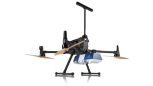
A UAV data set of approximately half an hour was collected around a farm in Reigate, England in April 2016. The UAV test duration is effectively limited by the capacity of the UAV’s battery which, with the payload deployed for this test, was limited to less than 15 min. To extend the test duration, approximately 10 min of static data was recorded at the beginning of the flight while the UAV was standing in the middle of the field with no obstruction around it. The data collection was performed with DJI S900 hexacopter shown in FIGURE 9 and a payload similar to that depicted in FIGURE 3. The patch antenna was mounted on ground plane with a 15 cm diameter to mitigate multipath effects and ensure the best signal reception possible. The RF signal was then split two-way and distributed to our rover receiver and a record and replay simulator. The RTCM correction stream was generated by a high-precision receiver connected to an antenna located on the roof of an office building in Reigate and made available on a server. Using a Raspberry Pi and a 3G modem the RTCM stream was forwarded to both our receiver and the recorder. This farm provides clear satellite visibility and is located approximately three kilometers away from the reference station. It meets all the regulatory requirements to recreationally fly a UAV. The tree-line test was carried to assess the ability of our RTK engine to recover from moderate signal degradations and dynamics. To this end, the UAV was flown repeatedly along the tree line shown in FIGURE 10.
[Click on an image to enlarge it.]


Test Data Processing
The UAV test data was processed in a similar fashion as the walk-test data. Two additional configurations, namely GPS/GLONASS RTK float (Flt-GR) and GPS RTK fixed (Fxd-G) were tested with the aim of illustrating their benefits and drawbacks. Due to payload weight restriction, it was not possible to embark a dual-frequency receiver for reference trajectory generation. Instead, the single-frequency raw measurements generated by the mass-market receiver were used. Recorded scenarios were replayed to a survey-grade receiver for performance benchmarking.
The main limitation of the UAV test setup is that the generation of the reference trajectory relies on raw measurements from our narrow-band single frequency rover receiver.. The lack of measurement redundancy and the increased probability of code multipath make the reference trajectory less reliable than that used during the walk test. However, UAV applications typically enjoy more favorable signal environment than their pedestrian counterparts. Additionally, it is possible to confirm the reliability of the reference trajectory using both the GrafNav backward/forward processing option and the reported accuracy.
However, the patch antenna used during the UAV test campaign is representative of mass-market applications. In fact, some tests have been conducted to compare the performance that could be achieved with various antenna types including, but not limited to, a high-precision antenna without its casing and a patch antenna with and without ground plane. The details of this investigation are beyond the scope of this article. Suffice to say that the performance of the patch antenna with a reasonably sized ground plane (15 cm in our case) was deemed the best compromise for mass-market applications in terms of size, weight and cost.
During the tree-line test, moderate signal degradations caused by trees are experienced by the receiver which cause the number of satellites to decrease at regular interval.
[Click on an image to enlarge it.]


FIGURES 11 to 14 show the resulting position error for the mass-market and high-precision receivers in Fxd-RD mode as well as those for the mass-marekt reeiver in Flt-GR and Fxd-G modes. The corresponding position error statistics are summarized in TABLE 2. Once again, this table can include position fixes that computed using code differential or RTK float mode.
Comparing the performance of the receivers in Fxd-GR mode, it can be seen that both receivers exhibit similar accuracy when they can fix ambiguities that the high-precision receiver suffers from an erroneous ambiguity fix at take-off which is also reflected in the position error 95 and 100 percentiles.
In Flt-GR mode the mass-market receiver is able to rapidly converge to dm-level accuracy. It is able to maintain this level of accuracy throughout the entire duration of test, highlighting the potential benefits of this mode for applications that do not require the highest level of accuracy but rely on smooth trajectory for guidance control.
For this test the mass-market receiver is able to fix ambiguity as often in Fixed-G mode than in Fixed-GR mode which is linked to the excellent satellite availability in the context of UAV applications. Additionally, the passes that were done close to the tree line were only performed later in the test, when ambiguities had already been fixed. This demonstrates the robustness of u-blox’s RTK engine to mild signal degradations. As a result, the NED position errors in Fxd-G mode are on par with those of the Fxd-GR mode. This highlights the potential benefits of this mode for high-dynamic applications that require higher navigation rate and operate in favorable signal environments.
[Click on an image to enlarge it.]


Conclusion
Static tests showed that with fewer than 20 tracking channels, a single frequency GPS/GLONASS or GPS/BeiDou RTK receiver can successfully fix ambiguities in a reasonable time frame. During the walk and UAV tests, the performance of the mass-market receiver is similar to that of high-end receivers with respect to position accuracy and availability. For example, the availability of the RTK fixed solution was shown to be excellent under open-sky conditions for both but, as expected, in presence of moderate signal degradation and increased receiver dynamics, the availability of the RTK fixed solution decreases in a similar way for both receivers.
The kinematic data sets also served to demonstrate the versatility of the new mass-market receiver’s RTK solution. More specifically, the usefulness of the float-only solution for applications that do not require the highest level of accuracy but rely on smooth trajectory for precise guidance was shown. Similarly, the value of the GPS-only solution for high-dynamic applications operating in favorable environment was highlighted.
Finally, it is important to remember that while the walk-test results shown were obtained using high-end antennas, the UAV test results were obtained using a low-cost patch antenna, validating the suitability of RTK technology for affordable mass-market applications.
Acknowledgments
The authors thank Oscar Miles for his support with the data collection efforts in Reigate, and Alex Parkins for his contributions to the design and implementation of the RTK engine.
Manufacturers
The mass-market receiver described here is manufactured by u-blox. The RTK technology comprises a rover (NEO M8P-0) and a reference station (NEO M8P-2).


Arno M.
I have Reach RTK kit by Emlid, I am using it for land survey on the ground (rather successfully). I am using it for about a year and it’s rather funny to see this article only now.