Positioning with Android: GNSS observables

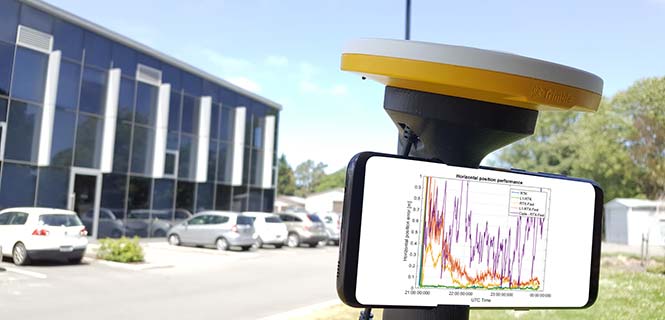
(Image: Authors/Trimble)
For those who want high accuracy, but don’t need it full time, high-productivity dedicated professional solutions may not be cost-justified. In these cases, a “positioning as a service” subscription could offer a viable use model.
Achieving precision positioning with just a standard mobile device, a correction stream using the mobile device’s data connection and a high-accuracy positioning application produces a very low barrier to achieving high accuracy.
By Stuart Riley, Herbert Landau, Victor Gomez, Nataliya Mishukova, Will Lentz and Adam Clare, Trimble Inc.
We expect that for professional applications that need precision positions, a dedicated system that employs a custom GNSS chipset and purpose-built applications will continue to be the right solution. However, it becomes clear that the ubiquity of consumer mobile devices, with increasing computing power, ruggedness and an expanding feature set, presents fertile ground for new development of improved positioning systems that don’t have strict professional requirements.
A range of new use models and applications will be enabled by consumer mobile phones with technology that improves positioning performance. The goal of the work presented here is to assess what level of performance can be achieved by using proprietary PVT (position, velocity, time) engines utilizing GNSS measurements from the Android GNSS measurement application programming interface (API).
We first review GNSS measurement and positioning performance from a subset of the current Android phones/tablets currently on the market. Then we show the position performance achievable using precision engine with measurements from a dual-frequency GNSS chipset targeted for the cellular handset market. This class of device is expected to be integrated into consumer cellular devices on the market within the next 1 to 2 years.
Performance of Current Phones
We tested various devices including the Nexus 9 (which provides phase data) and various other Android devices that implement the new API. Most devices tested do not support phase data; of the few devices tested that do provide phase data, all except the Nexus 9 implement GNSS power duty cycling. This is a mode where the GNSS chipset is only active for a fraction of each second to reduce power consumption. This results in cycle slips each epoch, which makes carrier-phase processing for real-time kinematic (RTK) unusable.
During the testing a wide range of performance across devices was observed. Figure 1 shows the C/NO for a high-elevation GPS satellite collected at the same time from two different Android models that implement the GNSS measurement API. The units were located in a clear environment less than a meter apart. Deep fades are present, most likely caused by deconstructive multipath.

Figure 1. Comparison of the C/NO from two different Android devices.
However, the devices show significantly different tracking performance: device B reports over 10 dB lower C/NO for much of the test and eventually stops reporting measurements. During our analysis, around six different Android devices have been tested; it isn’t clear whether the devices tested are typical over a broader population of device types.
Before attempting to position with observables from Android devices the measurement quality was analyzed. As only a subset of current devices that support the API provide phase information we wanted to evaluate both a phase-based RTK engine and a pseudorange/Doppler based code engine to determine what is possible from each class of device.
One of the devices tested was a Samsung S7 device. It provides pseudorange, Doppler and phase via the GNSS measurement API. However, the phone implements power duty cycling so after a short period of operation the duty cycling mode was enabled which resulted in a cycle slip on the phase every epoch.
To derive an improved position from this class of device pseudorange and Doppler can be fed into a code-phase positioning engine. Fortunately, the Doppler provided by the device is of reasonable quality as can be seen from Figure 2.
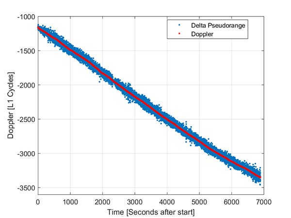
Figure 2. Android GNSS observables: Doppler versus time-differenced pseudorange.
In this simple analysis measurements from a single high elevation satellite were analyzed. The Doppler is plotted along with the differenced pseudorange converted into L1 cycles. It can be seen that as expected the Doppler has much lower noise and so can be used in a pseudorange smoother.
A simple way to view the pseudorange noise is to subtract the carrier phase from the pseudorange. If there are no cycle slips this should show ionospheric divergence with the noise dominated by the pseudorange noise. The absolute level is arbitrary as it includes integer carrier cycles. Figure 3 shows an example from an Android device.
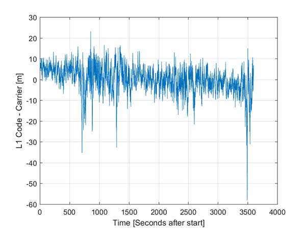
Figure 3. Android GNSS observables: pseudorange — carrier phase.
The data was captured on a building roof in an open environment. There’s a slight downward trend due to the ionospheric divergence between code and carrier, but the metric is dominated by the pseudorange noise. For this example from a high elevation GPS satellite the standard deviation is 6.5 meters. For comparison, a precision receiver connected to a precision GNSS antenna providing unsmoothed pseudorange in this environment would have a standard deviation of a few decimeters.
Another way to assess the measurement performance is to form double difference residuals. Data was logged from pairs of identical devices mounted with a common orientation. An RTK system was used to measure the same point on each device. The camera lens location above the screen was used as the reference point.
An accurate vector between the two references points was computed and used as truth in a double-difference residual analysis. Even though we do not know the precise location of the phase center of the antenna, because the difference was performed between two devices that are the same model and have the same orientation the error in the phase center location is common and will cancel. Various pairs of devices were tested by being mounted on a wooden board on a tripod at approximately waist height. The test configuration is shown in Figure 4.
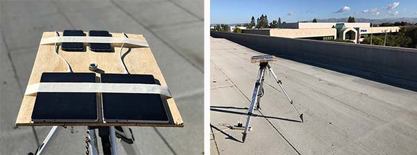
Figure 4. Android device test configuration.
Figure 5 provides the double difference GPS L1 C/A pseudorange residuals between two Android devices. We see errors beyond 100 meters and a standard deviation across all data of 14.4 meters. A precision system (RTK or RTX/PPP) would use a standard survey quality base or network of bases and not an Android device for the correction data.

Figure 5. Short baseline double-difference pseudorange, Android devices.
Consequently in a typical operating mode where a precision data stream provides corrections, the contribution in a double difference from the pseudorange on the Android devices would be roughly half the Android-to-Android residual seen in this test or approximately 7.2 meters for this example.
For comparison, the same metric was generated between two precision GNSS units connected to antennas on the same roof. While the data was not from the same time period, we observe very consistent performance over time.
Figure 6 shows the same pseudorange double difference across a short baseline over 24 hours. When comparing Figures 5 and 6, note the difference in the scale on the pseudorange residual axis. The standard deviation from a pair of precision devices is 53 centimeters (cm) or 27 times lower noise than an example pair of Android devices.
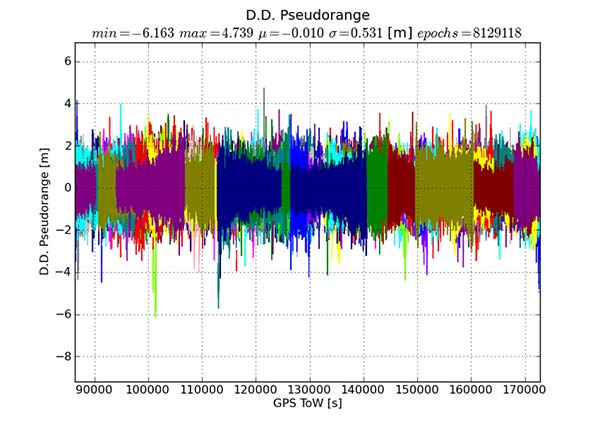
Figure 6. Short baseline double-difference pseudorange, precision devices.
All phones that provide GNSS measurements via the Android API publish the phase data in the accumulated delta range field. An accumulated delta range is not necessarily a full phase measurement; it can have an arbitrary starting phase.
For example, in a precision GNSS receiver, if the receiver locks to a satellite and some time later locks a second channel to the same satellite, the phase measurement from the two channels may have a different integer cycle component, but the subcycle component would be the same except for millimetric tracking noise.
If the two channels are providing accumulated delta range the initial phase offset may differ by up to one cycle. From the population of Android devices that publish phase that we have tested we have not observed any devices that deliver true full phase.
They all deliver an accumulated delta range with an arbitrary phase offset. This limits a phase engine to float processing and ambiguity fixing is not possible. The Android phase data collected from the previously described experiment was processed to provide the double difference carrier residuals. This is shown in Figure 7.
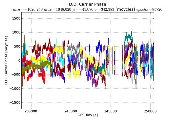
Figure 7. Short baseline double-difference phase residuals, Android devices.
The y-axis is in millicycles (1,000 millicycles = 1 cycle or approximately 19 cm for L1 GPS). Jumps are seen as the reference satellite changes or when the measurements have cycle slips. In this case the standard deviation is 342 millicycles. A double difference residual on a precision receiver in a similar environment with a high-quality antenna on a short baseline is an order of magnitude lower than this.
Another useful metric to review are the number of reported cycle slips. Figures 8 and 9 show a comparison of the cycle slips reported on GPS L1 C/A from an Android device compared to data logged on a precision receiver over the same time span. The receiver tends to only cycle slip at low elevation; the device had a zero-degree mask. The Android GNSS device cycle slips at higher elevations, probably a result of deep multipath fades due to the poorer antenna.
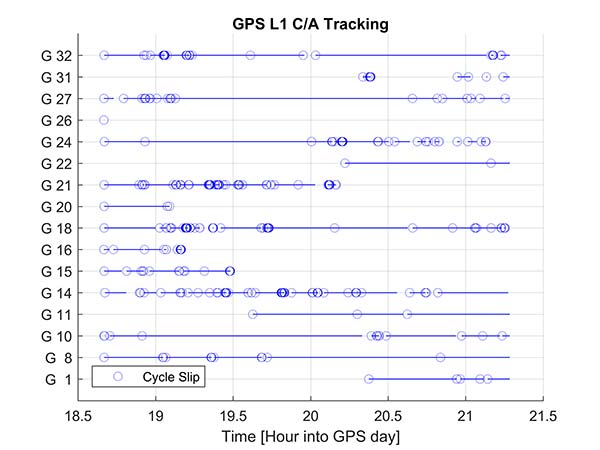
Figure 8. Cycle slips, Android device.
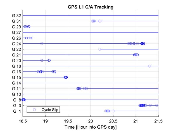
Figure 9. Cycle slips, precision device.
In an ION GNSS+ 2017 paper, we showed the achievable position performance using an RTK engine that had been previously customized to operate with measurements from consumer GNSS chipsets. It operated in a float mode due to the sub-cycle issue found in phase data from Android devices.
We also demonstrated the performance from a precision code-based PVT engine that had changes to the a priori measurement error estimate, a modified pseudorange/Doppler Hatch filter and used SBAS data to correct the position. As very few current Android devices deliver phase information the two engines were used to analyze what is possible today with the pseudorange and may be available in the future as phase is more universally available.
Data was processed from a Nexus 9 tablet, the only known Android device that has GNSS power duty cycling disabled. The unit was unmodified and so the Android tablet’s integrated GNSS antennas were used. The 2D performance is given in Table 1.

Table 1. 2D performance from Nexus 9 Android tablet.
Only GPS L1 and GLONASS L1 measurements were used and the RTK float solution delivered similar performance to the pseudorange solution. This is due to a combination of issues, very high pseudorange noise, and a significant number of cycle slips (see Figures 5 and 8). Only single frequency data was available, and while the engines used had been tuned for consumer data, they were not specifically designed for this class of data.
Next-Generation Phones
Within the next couple of years improved chipsets are expected to be available to consumers that will result in improvements in achievable positioning performance. In May 2017, Broadcom provided us with a development kit for its next generation L1/L5 multi-system BCM47755 GNSS chipset. This allowed us to assess what may be possible when improved GNSS chipsets are integrated in the next generation of cellular devices.
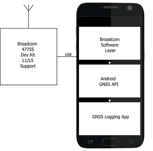
Figure 10. Broadcom BCM47755 development system.
The development environment included the GNSS chipset with an external antenna port so both a cell-phone equivalent antenna and a precision antenna could be compared. This allowed us to evaluate the impact of the antenna performance on the GNSS observables and positioning results. The Broadcom GNSS development system communicates via USB to a Samsung S7 phone and publishes data via the Android GNSS measurement API so the equivalent data flow of an integrated cellular device is maintained (see Figure 10).
In our ION paper, we showed the typical phase double-difference residuals observed from current Android devices. The Broadcom BCM47755 originally provided similar performance, although it also supports GPS L5 and Galileo E5A. In November 2017, Broadcom provided a firmware update that resolved the sub-cycle phase issues. With the updated Broadcom software, the double difference carrier residuals for GPS L1 on a zero baseline when differencing a precision receiver to a Broadcom BCM47755 are shown in Figure 11.
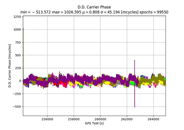
Figure 11. Precision GNSS to Broadcom BCM47755 zero baseline double difference carrier-phase residuals.
The standard deviation is 45 millicycles which is approximately 8.6 millimeters (mm). This is substantially better than earlier implementations of the Android GNSS interface (see Figure 7) and sufficient to perform RTK ambiguity resolution.
The rest of the results in this article were obtained with the improved firmware along with a new precision position engine. This engine was designed from inception to support GNSS measurements with differing quality and so can more optimally process the Android GNSS data. The effect of the improvements to the Broadcom firmware and the change in the processing engine can be seen if the results in our ION paper are compared to the data in this section.
To attempt to model what may be possible with a phone based on a next-generation chipset, a cell-phone equivalent antenna provided by Broadcom was used in some of the tests with the development system, as shown in Figure 12. This device has separate feeds for L1 and L5.

Figure 12. Cellular equivalent antenna.
Datasets were collected with the multi-frequency GNSS BCM47755 device. The data was captured in the Android GNSS measurement API format and converted to proprietary format files for further processing. All data was collected in Sunnyvale, California.
Measurements from GPS L1/L5, Galileo L1/E5A, GLONASS L1 and BeiDou B1 were logged and analyzed. The Precise Positioning Engine (PPE) allows performing carrier-phase RTX and RTK and a pseudorange-based solution using the RTX corrections. Tests were performed by using a precision antenna and a cell-phone equivalent GNSS antenna.
With Precision GNSS Antenna
These datasets were collected on a zero baseline with a precision receiver to allow a direct comparison of results with a professional receiver. The first test was on Nov. 22, 2017, where the Broadcom GNSS chip and the receiver were connected to the same professional antenna.
As seen in Figure 13, both GNSS receivers provide centimeter-level accuracies after some convergence time. With the current satellite constellations, only a third of the GPS satellites have L5 and only about half of the E5-capable Galileo constellation is in space. During this 3.5-hour test, the number of dual-frequency measurements processed by the engine that used the Broadcom chipset — data that does not support L2 — ranged between 6 and 10 satellites (Figure 14).
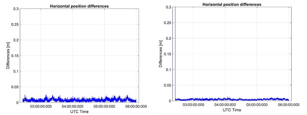
Figure 13. RTK performance for a 3.5-hour dataset sampled on Nov 22. Broadcom chip at left and precision chip at right. A short baseline was used — precision antenna.

Figure 14. Number of GPS L1/L5 plus Galileo E1/E5A dual-frequency measurements used by the position solution based on the Broadcom chipset — precision antenna.
Convergence times were measured with post-processing tools by splitting the datasets into individual time spans. Figure 15 shows that the consumer GNSS chipset is able to get fixed ambiguity solutions but it takes considerably more time (266 seconds versus 4 seconds) for the 95% of initializations. However, the system is fixing ambiguities and provides centimeter level positioning.
The same datasets were also processed with RTX-Fast in California. Thus the base station data was replaced by a global/regional correction stream received from an internet-based data source (Figure 16).
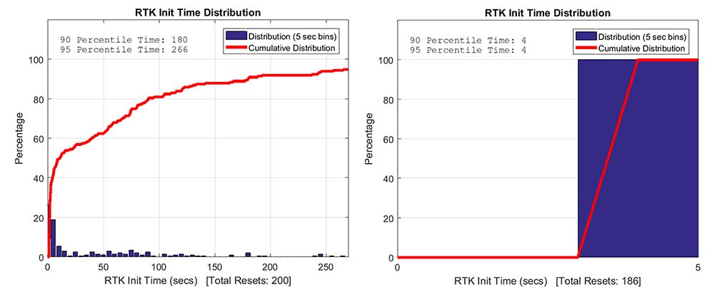
Figure 15. RTK initialization performance, dataset sampled on Nov 22. Broadcom chip at left and precision receiver at right — precision antenna.
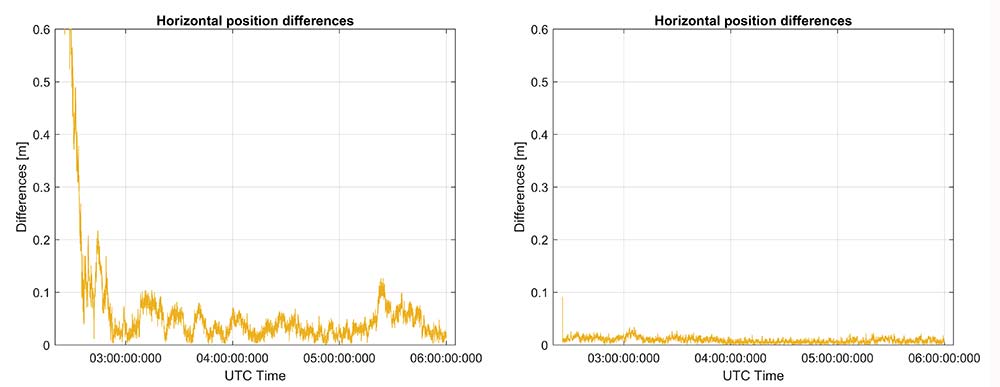
Figure 16. RTX performance for a 3.5 hour dataset sampled on Nov. 22 (Broadcom chip at left and Trimble chip at right) — precision antenna.
Horizontal accuracy for Broadcom reach 10 cm while the precision receiver reaches better than 3 cm. The degradation is in part due to the difference in quality of the carrier phase and the different number of dual frequency satellites processed. Precision devices provide measurements on E1/L1, L2 and L5/E5 providing at least dual frequency data from GPS, GLONASS, Galileo, BeiDou and QZSS.
The Broadcom chipset tested provided dual frequency GPS and Galileo along with single-frequency GLONASS and BeiDou; however, due to limited BeiDou constellation visible in California, data from this constellation was not used.
Convergence was also analyzed and is shown in Figure 17. From the data, we generated 24 convergence runs by taking one hour, progressively shifting the start time by 5 minutes and running the data with different start times through the PPE engine. This produced 24 runs, which were translated into 68% and 95% convergence statics shown.

Figure 17. RTX convergence performance for a 3.5-hour dataset sampled on Nov. 22. Broadcom chip at left and precision chip at right — precision antenna.
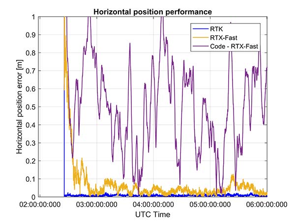
Figure 18. Code RTX performance for 3.5-hour dataset sampled Nov. 22 and corresponding RTK and RTX phase solutions — precision antenna.
The RTX-Fast solution for Broadcom reaches 30 cm horizontal error in 68% of the cases in approximately 12 minutes. The RTX-Fast convergence using precision GNSS data is near instantaneous as can be seen in the right of Figures 16 and 17, reaching centimeter accuracy.
The code position solution using the RTX correction stream provides sub-meter positioning (Figure 18).
As a summary, the cumulative distribution function plots (Figure 19) show the performance differences for this static environment, on Nov. 22.
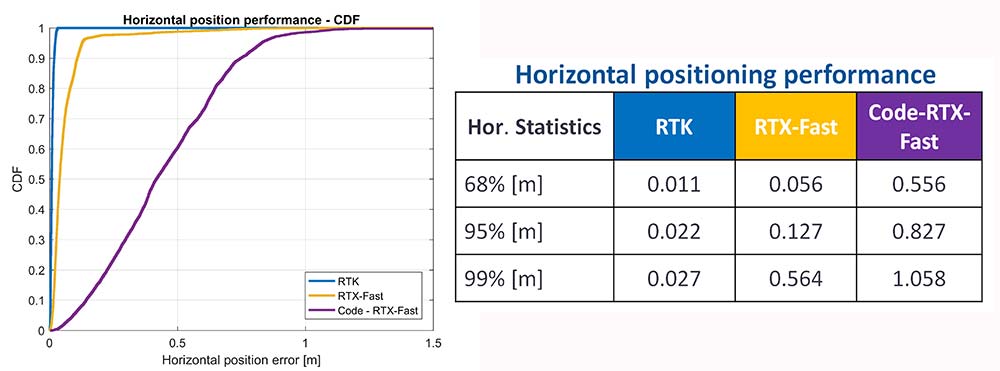
Figure 19. CDF plots for the different PPE position solutions — precision antenna.
Cell-Phone GNSS Antenna Results
Similar tests were performed using an external cell-phone GNSS antenna, which is close to the antenna used in a typical smartphone. RTK performance shows centimeter-level accuracies and reasonable convergence times, which are slightly worse than the results with the professional antenna (Figures 20–24).
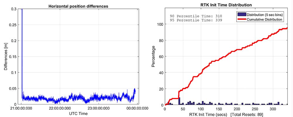
Figure 20. RTK positioning and initialization performance for the Broadcom chip and the cell antenna sampled on Nov 20 — cell-phone GNSS antenna.
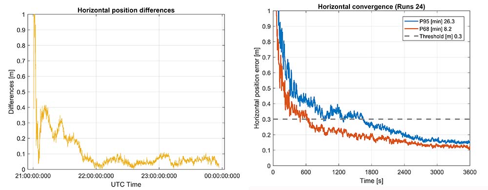
Figure 21. RTX-Fast positioning and convergence performance for the Broadcom chip and the cell antenna sampled on Nov. 20 — cell-phone GNSS antenna.
In general as expected we achieve worse performance when connected to the GNSS cell-phone antenna for all the different positioning modes. For the cell antenna we also generated single-frequency RTK and single-frequency RTX-Fast position solutions and compare it with a code positioning solution.
Positioning Engine in Android
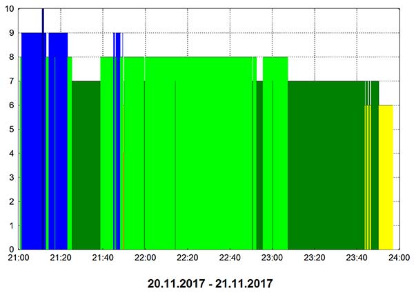
Figure 22. Number of GPS L1/L5 plus Galileo E1/E5A dual-frequency measurements used by the position solution based on the Broadcom chipset — cell-phone GNSS antenna.
The results presented in this article captured GNSS data using the Android API and then post-processed the data using PC versions of the position engines. A significant amount of data has been captured and analyzed using this method.
For the purpose of real-world demonstration the PPE has been implemented in an Android app to be used in cell phone devices. This PPE is able to provide RTK, RTX and code based positioning technology in one single PPE library.
The app has been tested running on a Samsung S7 connected to Broadcom’s new chipset development kit as well as a Nexus 9 tablet that uses an older generation GNSS chipset.
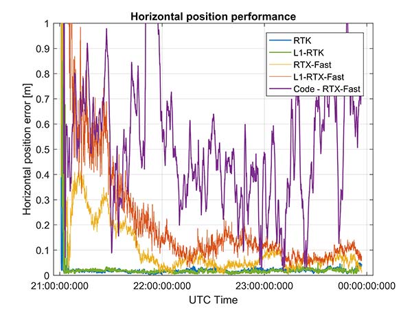
Figure 23. Code RTX performance, the dataset sampled Nov. 20 and corresponding RTK and RTX phase solutions — cell-phone GNSS antenna.
Future work will refine this solution as well as evaluate how well the system works when mobile. The data collected in this article operated in an environment with a clear view of the sky. We plan to characterize what happens when the platform moves with both pedestrian and automotive dynamics, as well as the effects of body masking and challenges with changes to the GNSS antenna reception pattern when the phone is held.
Summary
While this article has highlighted that sub-meter and centimeter accuracy have been achieved in a laboratory environment, there are many challenges to be addressed before centimeter accuracy in a phone can be achieved with performance suitable for users in real-world environments.
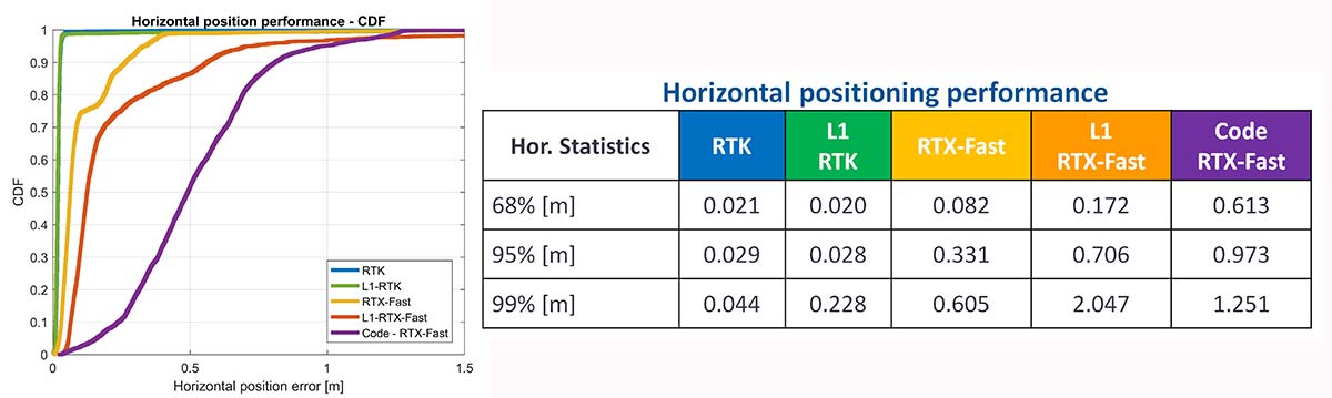
Figure 24. CDF plots for the different PPE position solutions for cell antenna dataset.
The challenges include very high multipath, significant differences in the tracking performance between different devices, and high rates of cycle slips. As very few Android-based devices provide continuous phase, a pseudorange/Doppler-based engine has been modified to accept Android data.
Based on the testing with existing devices it is possible to achieve position solutions of 1–2-meter accuracy in ideal static scenarios. This is a significant improvement in accuracy for Android based devices.
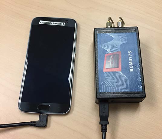
Figure 25. PPE engine on a Samsung S7 with a Broadcom BCM4775 evaluation kit.
However, as performance differences were observed between different mobile devices significantly more data needs to be collected over a larger set of devices to review the repeatability of these preliminary results from existing Android devices.
The Broadcom BCM47755 development kit for a dual-frequency GNSS chipset intended for future phones has allowed us to review the potential position performance that may be achievable in a handset in a few years.
By connecting this next-generation GNSS chipset to a GNSS antenna typical of a cellular device and comparing the performance from a precision GNSS antenna, we’ve shown for the first time that it is possible to produce precision positions from a static cellular class GNSS device in ideal conditions at the centimeter level with both an RTK solution and a PPP solution.
However, due to the significantly higher measurement noise and high multipath from the cellular device’s GNSS antenna, the convergence times to reach centimeter level remain a challenge; although using dual-frequency phase data from a cellular GNSS chipset with a PPE and RTX service, the position is very rapidly sub-meter.
Future work will focus on analyzing how the performance changes when operating in the normal user environment. The effects on the measurements of user motion, body masking and de-tuning of the antenna when the device is held need to be quantified. The Nexus 9 tablet used in this article does not have integrated cellular. The Broadcom development kit connects to the phone via a cable and is also not integrated into the handset.
We will be evaluating what may happen with a more integrated unit to make sure emissions from devices with integrated cellular very close to the GNSS antenna do not result in further degradation.
As the position performance is very sensitive to the quality of the antenna from both multipath and cycle slips due to low C/NO and deep fades, we’ll also evaluate how well the performance of the PCB-based GNSS antenna, which is part of the BCM47755 evaluation kit, matches current handsets.
Acknowledgment
This article further develops work first shown in an ION GNSS+ 2017 paper, “On the Path to Precision — Observations with Android GNSS Observables.”
Manufacturers
Trimble CenterPoint RTX is the satellite orbit and clock corrections service used here, enabling a PPP-like positioning with ambiguity fixing, providing better than 4 cm with typically less than 10 minutes’ convergence.
RTX-Fast functionality in Europe and parts of California uses regional atmospheric models to provide better than 4-cm horizontal in typically less than one minute. When precision and professional receivers and RTK engines are mentioned in this article, they are Trimble devices, the BD940 receiver in some cases.
A Trimble Zephyr 3 antenna was used in many tests shown here.


Subscribe to GPS World
If you enjoyed this article, subscribe to GPS World to receive more articles just like it.


Follow Us