GNSS RF Compatibility Assessment: Interference among GPS, Galileo, and Compass

By Wei Liu, Xingqun Zhan, Li Liu, and Mancang Niu
A comprehensive methodology combines spectral-separation and code-tracking spectral-sensitivity coefficients to analyze interference among GPS, Galileo, and Compass. The authors propose determining the minimum acceptable degradation of effective carrier-to-noise-density ratio, considering all receiver processing phases, and conclude that each GNSS can provide a sound basis for compatibility with other GNSSs with respect to the special receiver configuration.
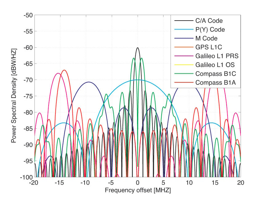
Power spectral densities of GPS, Galileo, and Compass signals in the L1 band.
As GNSSs and user communities rapidly expand, there is increasing interest in new signals for military and civilian uses. Meanwhile, multiple constellations broadcasting more signals in the same frequency bands will cause interference effects among the GNSSs. Since the moment Galileo was planned, interoperability and compatibility have been hot topics. More recently, China has launched six satellites for Compass, which the nation plans to turn into a full-fledged GNSS within a few years. Since Compass uses similar signal structures and shares frequencies close to other GNSSs, the radio frequency (RF) compatibility among GPS, Galileo, and Compass has become a matter of great concern for both system providers and user communities.
Some methodologies for GNSS RF compatibility analyses have been developed to assess intrasystem (from the same system) and intersystem (from other systems) interference. These methodologies present an extension of the effective carrier power to noise density theory introduced by John Betz to assess the effects of interfering signals in a GNSS receiver. These methodologies are appropriate for assessing the impact of interfering signals on the processing phases of the receiver prompt correlator channel (signal acquisition, carrier-tracking loop, and data demodulation), but they are not appropriate for the effects on code-tracking loop (DLL) phase. They do not take into account signal processing losses in the digital receiver due to bandlimiting, sampling, and quantizing. Therefore, the interference calculations would be underestimated compared to the real scenarios if these factors are not taken into account properly. Based on the traditional methodologies of RF compatibility assessment, we present here a comprehensive methodology combining the spectral separation coefficient (SSC) and code tracking spectral sensitivity coefficient (CT_SSC), including detailed derivations and equations.
RF compatibility is defined to mean the “assurance that one system will not cause interference that unacceptably degrades the stand-alone service that the other system provides.” The thresholds of acceptability must be set up during the RF compatibility assessment. There is no common standard for the required acceptability threshold in RF compatibility assessment. For determination of the required acceptability thresholds for RF compatibility assessment, the important characteristics of various GNSS signals are first analyzed, including the navigation-frame error rate, probability of bit error, and the mean time to cycle slip. Performance requirements of these characteristics are related to the minimum acceptable carrier power to effective noise power spectral density at the GNSS receiver input. Based on the performance requirements of these characteristics, the methods for assessing the required acceptability thresholds that a GNSS receiver needs to correctly process a given GNSS signal are presented.
Finally, as signal spectrum overlaps at L1 band among the GPS, Galileo, and Compass systems have received a lot of attention, interference will be computed mainly on the L1 band where GPS, Galileo, and Compass signals share the same band. All satellite signals, including GPS C/A, L1C, P(Y), and M-code; Galileo E1, PRS, and E1OS; and Compass B1C and B1A, will be taken into account in the simulation and analysis.
Methodology
To provide a general quantity to reflect the effect of interference on characteristics at the input of a generic receiver, a traditional quantity called effective carrier-power-to-noise-density (C/N0), is noted as (C/N0)eff_SSC. This can be interpreted as the carrier-power-to-noise-density ratio caused by an equivalent white noise that would yield the same correlation output variance obtained in presence of an interference signal. When intrasystem and intersystem interference coexist, (C/N0)eff_SSC can be expressed as
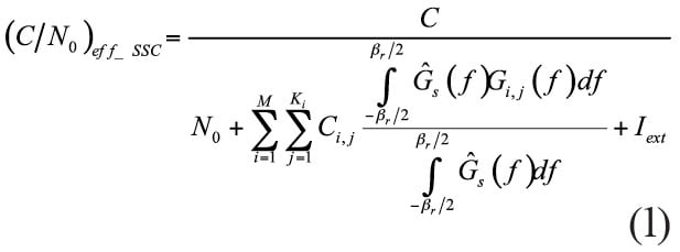
Ĝs(f) is the normalized power spectral density of the desired signal defined over a two-sided transmit bandwith ßT, C is the received power of the useful signal. N0 is the power spectral density of the thermal noise. In this article, we assume N0 to be –204 dBW/Hz for a high-end user receiver. Ĝi,j(f) is the normalized spectral density of the j-th interfering signal on the i-th satellite defined over a two-sided transmit bandwith ßT, Ci,j the received power of the j-th interfering signal on the i-th satellite, ßr the receiver front-end bandwidth, M the visible number of satellites, and Ki the number of signals transmitted by satellite i. Iext is the sum of the maximum effective white noise power spectral density of the pulsed and continuous external interference.
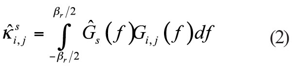
It is clear that the impact of the interference on (C/N0)eff_SSC is directly related to the SSC of an interfering signal from the j-th interfering signal on the i-th satellite to a desired signal s, the SSC is defined as
From the above equations it is clear that the SSC parameter is appropriate for assessing the impact of interfering signals on the receiver prompt correlator channel processing phases (acquisition, carrier phase tracking, and data demodulation), but not appropriate to evaluate the effects on the DLL phase. Therefore, a similar parameter to assess the impact of interfering signals on the code tracking loop phase, called code tracking spectral sensitivity coefficient (CT_SSC) can be obtained. The CT_SSC is defined as
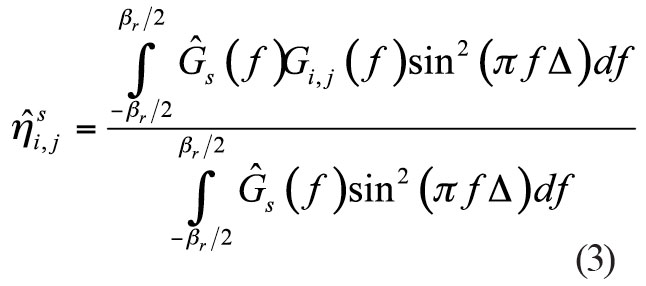
where Δ is the two-sided early-to-late spacing of the receiver correlator.
To provide a metric of similarity to reflect the effect of interfering signals on the code tracking loop phase, a quantity called CT_SSC effective carrier power to noise density (C/N0), denoted (C/N0)eff_CT_SSC, can be derived. When intrasystem and intersystem interference coexist, this quantity can be expressed as
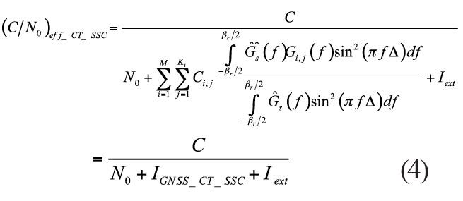
where IGNSS_CT_SSC is the aggregate equivalent noise power density of the combination of intrasystem and intersystem interference.
Equivalent Noise Power Density. When more than two systems operate together, the aggregate equivalent noise power density IGNSS ( IGNSS_SSC or IGNSS_CT_SSC ) is the sum of two components
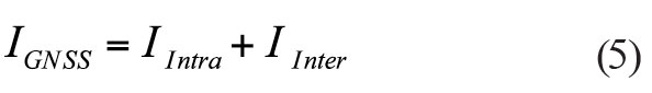
IIntra is the equivalent noise power density of interfering signals from satellites belonging to the same system as the desired signal, and IInter is the aggregate equivalent noise power density of interfering signals from satellites belonging to the other systems.
In fact, recalling the SSC and CT_SSC definitions, hereafter, denoted  or
or  as
as  , the equivalent noise power density (IIntra or IInter) can be simplified as
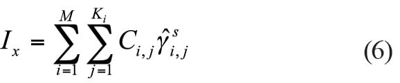
where Ci,j is the user received power of the j-th signal belonging to the i-th satellite, as determined by the link budget.
For the aggregate equivalent noise power density calculation, the constellation configuration, satellite and user receiver antenna gain patterns, and the space loss are included in the link budget. User receiver location must be taken into account when measuring the interference effects.
Degradation of Effective C/N0. A general way to calculate (C/N0)eff, (C/N0)eff_SSC , or (C/N0)eff_CT_SSC introduced by interfering signals from satellites belonging to the same system or other systems is based on equation (1) or (4). In addition to the calculation of (C/N0)eff , calculating degradation of effective C/N0 is more interesting when more than two systems are operating together. The degradation of effective C/N0 in the case of the intrasystem interference in dB can be derived as
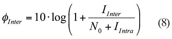
Similarly, the degradation of effective C/N0 in the case of the intersystem interference is
Bandlimiting, Sampling, and Quantization. Traditionally, the effect of sampling and quantization on the assessment of GNSS RF compatibility has been ignored. Previous research shows that GNSS digital receivers suffer signal-to-noise-plus interference ration (SNIR) losses due to bandlimiting, sampling, and quantization (BSQ). Earlier studies also indicate a 1.96 dB receiver SNR loss for a 1-bit uniform quantizer. Therefore, the specific model for assessing the combination of intrasystem and intersystem interference and BSQ on correlator output SNIR needs to be employed in GNSS RF compatibility assessment.
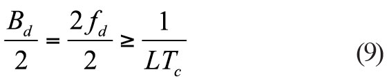
Influences of Spreading Code and Navigation Data. In many cases, the line spectrum of a short-code signal is often approximated by a continuous power spectral density (PSD) without fine structure. This approximation is valid for signals corresponding to long spreading codes, but is not appropriate for short-code signals, for example, C/A-code interfering with other C/A-code signals. As one can imagine, when we compute the SSC, the real PSDs for all satellite signals must be generated. It will take a significant amount of computer time and disk storage. This fact may constitute a real obstacle in the frame of RF compatibility studies. Here, the criterion for the influences of spreading code and navigation data is presented and an application example is demonstrated. For the GPS C/A code signal, a binary phase shift keying (BPSK) pulse shape is used with a chip rate fc = 1.023 megachips per seconds (Mcps). The spreading codes are Gold codes with code length N = 1023. A data rate fd = 50 Hz is applied. As shown in Figure 1, the PSD of the navigation data (Gd(f) = 1/fd sin c2 (f/fd) ) replace each of the periodic code spectral lines. The period of code spectral lines is T = 1/LTC. The mainlobe width of the navigation data is Bd =2fd.
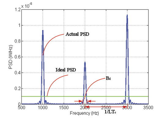
Figure 1. Fine structure of the PSD of GPS C/A code signal (fd = 50 Hz ,without
logarithm operation).
For enough larger data rates or long spreading codes, the different navigation data PSDs will overlap with each other. The criterion can be written as:
Finally,
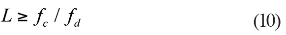
When criterion L ≥ fc/fd is satisfied, navigation signals within the bandwidth are close to each other and overlap in frequency domain. The spreading code can be treated as a long spreading code, or the line spectrum can be approximated by a continuous PSD.
C/N0 Acceptability Thresholds
Receiver Processing Phase. The determination of the required acceptability thresholds consider all the receiver processing phases, including the acquisition, carrier tracking and data demodulation phases.The signal detection problem is set up as a hypothesis test, testing the hypothesis H1 that the signal is present verus the hypothesis H0 that the signal is not present. In our calculation, the detection probability pd and the false alarm probability pf are chosen to be 0.95 and 10–4, respectively. The total dwell time of 100 ms is selected in the calculation.
A cycle slip is a sudden jump in the carrier phase observable by an integer number of cycles. It results in data-bit inversions and degrades performance of carrier-aided navigation solutions and carrier-aided code tracking loops. To calculate the minimum acceptable signal C/N0 for a cycle-slip-free tracking, the PLL and Costas loop for different signals will be considered. A PLL of third order with a loop filter bandwidth of 10 Hz and the probability of a cycle slip of 10–5 are considered. We can find the minimum acceptable signal C/N0 related to the carrier tracking process. For the scope of this article, the vibration induced oscillator phase noise, the Allan deviation oscillator phase noise, and the dynamic stress error are neglected.
In terms of the decoding of the navigation message, the most important user parameters are the probability of bit error and the probability of the frame error. The probability of frame error depends upon the organization of the message frame and various additional codes. The probability of the frame error is chosen to be 10–3. For the GPS L1C signal using low-density parity check codes, there is no analytical method for the bit error rate or its upper bound. Due to Subframe 3 data is worst case, the results are obtained via simulation. In this article, the energy per bit to noise power density ratio of 2.2 dB and 6 dB reduction due to the pilot signal are taken into account, and the loss factor of the reference carrier phase error is also neglected.
Minimum Acceptable Degradation C/N0. The methods for accessing the minimum acceptable required signal C/N0 that a GNSS receiver needs to correct
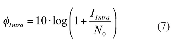
ly process a desired signal are provided above. Therefore, the global minimum acceptable required signal carrier to noise density ratio (C/N0)global_min for each signal and receiver configuration can be obtained by taking the maximum of minima. In addition to the minimum acceptable required signal C/N0, obtaining the minimum acceptable degradation of effective C/N0 is more interesting in the GNSS RF compatibility coordination. For intrasystem interference, when only noise exists, the minimum acceptable degradation of effective C/N0 in the case of the intrasystem interference can be defined as
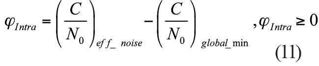
Similarly, the minimum acceptable degradation of effective C/N0 in the case of the intersystem interference can be expressed as
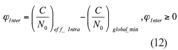
Table 1 summarizes the calculation methods for the minimum acceptable required of degradation of effective C/N0.
Simulation and Analysis
Table 2 summarizes the space constellation parameters of GPS, Galileo, and Compass.
For GPS, a 27-satellite constellation is taken in the interference simulation. Galileo will consist of 30 satellites in three orbit planes, with 27 operational spacecraft and three in-orbit spares (1 per plane). Here we take the 27 satellites for the Galileo constellation. Compass will consist of 27 MEO satellites, 5 GEO, and 3 IGSO satellites. As Galileo and Compass are under construction, ideal constellation parameters are taken from Table 2.
Signals Parameters. The PSDs of the GPS, Galileo and Compass signals in the L1 band are shown in the opening graphic. As can be seen, a lot of attention must be paid to signal spectrum overlaps among these systems. Thus, we will concentrate only on the interference in the L1 band in this article. All the L1 signals including GPS C/A, L1C, P(Y), and M-code; Galileo E1 PRS and E1OS; and Compass B1C and B1A will be taken into account in the simulation and analysis.
Table 3 summarizes GPS, Galileo and Compass signal characteristics to be transmitted in the L1 band.
Simulation Parameters. In this article, all interference simulation results refer to the worst scenarios. The worst scenarios are assumed to be those with minimum emission power for desired signal, maximum emission power for all interfering signals, and maximum (C/N0)eff degradation of interference over all time steps. Table 4 summarizes the simulation parameters considered here.
SSC and CT_SSC. As shown in expression (1) or (4), (C/N0)eff is directly related to SSC or CT_SSC of the desired and interfering signals. Figure 2 and Figure 3 show both SSC and CT_SSC for the different interfering signals and for a GPS L1 C/A-code and GPS L1C signal as the desired signal, respectively. The figures obviously show that CT_SSC is significantly different from the SSC. The results also show that CT_SSC depends on the early-late spacing and its maximal values appear at different early-late spacing.

FIGURE 2. SSC and CT_SSC for GPS C/A-code as desired signal.

FIGURE 3. SSC and CT_SSC for GPS L1C as desired signal.
The CT_SSC for different civil signals in the L1 band is calculated using expression (3). The power spectral densities are normalized to the transmitter filter bandwidth and integrated in the bandwidth of the user receiver. As we saw in expression (3), when calculating the CT_SSC, it is necessary to consider all possible values of early-late spacing. In order to determine the maximum equivalent noise power density (IIntra or IInter), the maximum CT_SSC will be calculated within the typical early-late spacing ranges (0.1–1 chip space).
Results and Analysis
In this article we only show the results of the worse scenarios where GPS, Galileo, and Compass share the same band. The four worst scenarios include:
◾ Scenario 1: GPS L1 C/A-code ← Galileo and Compass (GPS C/A-code signal is interfered with by Galileo and Compass)
◾ Scenario 2: GPS L1C ← Galileo and Compass (GPS L1C signal is interfered with by Galileo and Compass)
◾ Scenario 3: Galileo E1 OS ← GPS and Compass (Galileo E1 OS signal is interfered with by GPS and Compass)
◾ Scenario 4: Compass B1C ← GPS and Galileo (Compass B1C signal is interfered with by GPS and Galileo)
Scenario 1. The maximum C/N0 degradation of GPS C/A-code signal due to Galileo and Compass intersystem interference is depicted in Figure 4 and Figure 5.
Scenario 2. Figure 6 and Figure 7 also show the maximum C/N0 degradation of GPS L1C signal due to Galileo and Compass intersystem interference.
Scenario 3. The maximum C/N0 degradation of Galileo E1OS signal due to GPS and Compass intersystem interference is depicted in Figure 8 and Figure 9.
Scenario 4. For scenario 4, Figure 10 and Figure 11 show the maximum C/N0 degradation of Compass B1C signal due to GPS and Galileo intersystem interference.
From the results from these simulations, it is clear that the effects of interfering signals on code tracking performance may be underestimated in previous RF compatibility methodologies. The effective carrier power to noise density degradations based on SSC and CT_SSC are summarized in Table 5. All the results are expressed in dB-Hz.
C/N0 Acceptability Thresholds. All the minimum acceptable signal C/N0 for each GPS, Galileo, and Compass civil signal are simulated and the results are listed in Table 6. The global minimum acceptable signal C/N0 is summarized in Table 7. All the results are expressed in dB-Hz.
Effective C/N0 Degradation Thresholds. All the minimum effective C/N0 for each GPS, Galileo and Compass civil signal due to intrasystem interference are simulated, and the results are listed in Table 8. Note that the high-end receiver configuration and external interference are considered in the simulations. According to the method summarized in Table 1, the effective C/N0 degradation acceptability thresholds can be obtained. The results are listed in Table 9.
As can be seen from these results, each individual system can provide a sound basis for compatibility with other GNSSs with respect to the special receiver configuration used in the simulations. However, a common standard for a given pair of signal and receiver must be selected for all GNSS providers and com
munities.


Conclusions
At a minimum, all GNSS signals and services must be compatible. The increasing number of new GNSS signals produces the need to assess RF compatibility carefully. In this article, a comprehensive methodology combing the spectral separation coefficient (SSC) and code tracking spectral sensitivity coefficient (CT_SSC) for GNSS RF compatibility assessment were presented. This methodology can provide more realistic and exact interference calculation than the calculation using the traditional methodologies. The method for the determination of the required acceptability thresholds considering all receiver processing phases was proposed. Moreover, the criterion for the influences of spreading code and navigation data was also introduced.
Real simulations accounting for the interference effects were carried out at every time and place on the earth for L1 band where GPS, Galileo, and Compass share the same band. It was shown that the introduction of the new systems leads to intersystem interference on the already existing systems. Simulation results also show that the effects of intersystem interference are significantly different by using the different methodologies. Each system can provide a sound basis for compatibility with other GNSSs with respect to the special receiver configuration in the simulations.
At the end, we must point out that the intersystem interference results shown in this article mainly refer to worst scenario simulations. Though the values are higher than so-called normal values, it is feasible for GNSS interference assessment. Moreover, the common standard for a given signal and receiver pair must be selected for and coordinated among all GNSS providers and communities.
This article is based on the ION-GNSS 2010 paper, “Comprehensive Methodology for GNSS Radio Frequency Compatibility Assessment.”
WEI LIU is a Ph.D. candidate in navigation guidance and control at Shanghai Jiao Tong University, Shanghai, China. XINGQUN ZHAN is a professor of navigation guidance and control at the same university. LI LIU and MANCANG NIU are Ph.D. candidates in navigation guidance and control at the university.


Subscribe to GPS World
If you enjoyed this article, subscribe to GPS World to receive more articles just like it.


Follow Us